
.png)
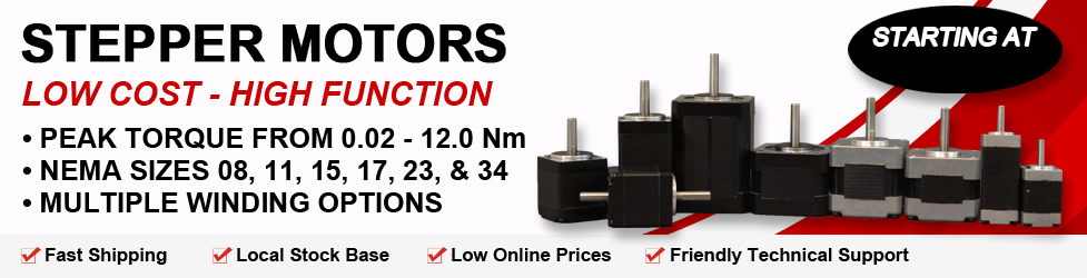
Kinco offers a large variety of stepper motors and drivers, to suit almost any stepper motor application. Stepper motors range from NEMA frame sizes 08 to 34, with single or double-ended shafts, with several different winding options in each motor size. The Kinco Stepper Motor Driver product line is compatible with Kinco stepper motors, as well as with most other Stepper Motor manufacturers. Kinco's high-performance stepper motor/driver product line is reliable, competitively priced, and stocked in Anaheim, California, USA. The products shown in this web site are standard, but customization is available. Cables, connectors, encoders, brakes, and gearboxes can be added. Contact us to discuss the specifics of your Stepper Motor driver application!
Stepper Motor Content-
Frequently Asked Questions
What temperatures are stepper motors able to run at?
Most stepper motors include Class B insulation. This allows the motor to sustain temperatures of up to 130° C. Therefore, with an ambient temperature of 40° C, the stepper motor has a temperature rise allowance of 90° C allowing for stepper motors to run at high temperatures.
What is the difference between four, six and eight leads in motors?
4 and 6 lead stepper motors are considered 2 phase motors. 8 lead stepper motors are considered to be 4 phase steppers. 4 lead motors can be wired in bipolar series connection only 6 lead motors can be wired in bipolar series, bipolar half-coil or uniploar connections 8 lead motors can be wired in bipolar series, bipolar half-coil, biploar parallel or uniploar connections.
What is the recommended cable distance between Kinco Automation stepper motors and drivers?
We recommend that the wiring between stepper motors and drivers not exceed 25 feet. Although it is not required, we suggest using Kinco Automation shielded motor cable. This cable is ideally suited to handle all driver and motor combinations that we offer. We can also add connectors to the cables. Please contact an Applications Engineer for more details.
What is the life expectancy of Kinco Automation Stepper Motors?
Kinco Automation stepper motors life expectancy is mainly based on the bearings. The majority of Kinco Automation stepper motors contain ball bearings providing 20,000 plus hours life expectancy under normal operating conditions. Kinco Automation's warranty is 12 months after the invoice date. See the "Environmental Conditions" sections of the stepper motor guide for more details.
What gauge wire should be used for a NEMA 34 stepper motor @ 10 feet of distance?
Kinco Automation motor cable is ideal. It is 16 gauge, 8 conductor with matching color code for the stepper motors carried by Kinco Automation. We can also add connectors for you if you prefer. See the Accessories section of our web site for more details.
Does Kinco Automation have Permanent Magnet Stepper Motors?
Yes. In size ranging from 15 to 57 mm in diameter, with torque ranges of 1 to 23 oz.-in. (model dependent). See PM Stepper Motors under the Stepper Motor category on our web site for more details and product specifications.
Can I order a stepper motor with 3% accuracy instead of 5%?
Because almost all of our 5% rated stepper motors fall into the 3% accuracy category, we usually recommend that you order our standard motors. If you require a "guarantee" for the 3% accuracy, contact the factory for assistance.
I need a stepper gearmotor. Does Kinco Automation offer these motors?
Yes. Kinco Automation offers stepper motors with Planetary Gearboxes in NEMA sizes 11, 17 and 23. We also have stepper motors with Spur Gearboxes in NEMA sizes 23 and 34, and PM stepper gearmotors in sized 24 to 42 mm diameters. Visit the Stepper Gearmotor section of our web site for more details. Please Note: We also offer gearboxes and motors separately, should you not find the size or gear ratio you require.
Does Kinco Automation make stepper motors with drivers attached?
Yes. Kinco Automation offers a line of Integrated Stepper Motors with Drivers and/or Controllers, in NEMA sizes 17, 23 and 34.Check our 17MD, 23MD, and 34MD series for Integrated Motor/Drivers, and our 17MDSI and 23MDSI series for our Integrated Motor/Driver/Controller product lines.
Can I purchase an IP65 rated Stepper Motor?
Yes. Kinco Automation offers a IP65 version for NEMA sizes 17, 23, 34 and 42 frame stepper motors, torque ranges from 35 to 5,700 oz.-in.(model specific). Visit our web site under Stepper Motors, and search IP65 motors.
What types of applications are encoders implemented in?
Encoders are frequently used in stepper motors, automation, robotics, medical devices, motion control and many other applications requiring position feedback.
Why does my stepper motor run hot?
Under normal operating conditions, stepper motors will run "hot." Always include adequate airflow in your stepper motor/driver system. Check the individual specification sheet for the stepper motor to be certain it is in the normal temperature range. If not, consult Kinco Automation's Application Engineers.
Can I order stepper motors with encoders added? How do I go about it?
Yes. Encoders can not only be added to stepper motors, but brushless motors as well. Please refer to our Encoders located under Accessories on our web site. Kinco Automation offers a line of single-ended or differential incremental rotary encoders. These encoders are available in sizes to cover NEMA 08 to 42 motors. These encoders have the capability to track from 0 to 100,000 cycles per second, with options of 32 to 2,500 cycles per revolution, with or without index features. Encoders are configured as motor adders, for dual shaft motors, or can be purchased separately, located on our Encoder web pages. Encoder cables are available, but also purchased separately.
Can Kinco Automation cross a PacSci stepper motor?
For many stepper motors models, Kinco Automation has a perfect cross for the PacSci motors, particularly in the PacSci N and K series, and the older KML series. We have Cross Reference lists on our web site, or you may contact an Kinco Automation Customer Service representative for more details.
Can Kinco Automation cross a SloSyn stepper motor?
For many stepper motors models, Kinco Automation has a perfect cross for the Superior Electric SloSyn stepper motors, particularly in the KML and MO60 and MO90 series. We have Cross Reference lists on our web site, or you may contact an Kinco Automation Customer Service representative for more details.
Can Kinco Automation cross an Automation Direct stepper motor?
Yes. For many stepper motors models, Kinco Automation has a good cross for the Automation Direct high-torque stepper motors. We have Cross Reference lists on our web site, or you may contact an Kinco Automation Customer Service representative for more details.
Are stepper motors accurate?
Yes, if you mean accuarte as in precise step/motion? The only inaccuracy associated with a stepper motor is a noncumulative positioning error which is measured in % of the step angle. Typically, stepper motors are manufactured within a 2-5% step accuracy, even better for some manufacturers.
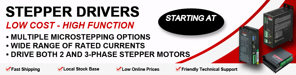
Compared to other stepper motor driver manufacturers, Kinco Automation offers a lot of microstep driver choices. Why so many models?
Kinco Automation has one of the broadest lines of stepper motor products in order to give customers as many options as possible, to gachieve the performance they desire in the most cost-effective solution. Typical microstep driver modes range from 'divide-by-8' to 'divide-by-256' (up to 51,200 steps per revolution for a 1.8 degree motor), which are dependent upon the driver series. Some microstep drivers have a fixed divisor, while the more expensive microstep drivers provide for selectable divisors, up to 256. In general, the larger the microstep divisor provided, the more costly the microstep driver. The higher the current range is, the more expensive the driver. So, to get customers more closely to the exact requirements, we offer a wide variety to choose from. Kinco Automation also manufactures a series of Integrated Stepper Motors/Drivers, meaning the stepper motor and microstep driver are in one unit. This design approach takes the guesswork out of motor and driver compatibility. For more information, please see the 17MD, 23MD and 34MD series.
What is the required maintenance for a stepper motor?
Since stepper motors are brushless, they require no maintenance for wear and tear on brushes and commutators. Keeping the environment clean will be helpful.
What is the ambient temperature of a stepper motor?
This depends on the class rating for the insulation. Kinco Automation's standard stepper motors are class B rated. This means an internal temperature of 130°C maximum on the internal windings. With the motors rated current in both windings, the temperature rise is 80°C. So 130°-80° is equal to 50°C maximum ambient temperature.
Is the HMI-ATO-LPS070 able to run a stepper motor?
Yes the HMI-ATO-LPS070 can operate two stepper motors simultaneously. This HMI has such features, speed control, position control, dual axis interpolation and can accept an encoder input for more accurate positioning. The max frequency that the HMI-ATO-LPS070 can output is 100 KHz but can only accurately count a PWM signal up to 400 Hz. If using an encoder one would have to use a less accurate encoder(less lines) or have to slow down there speed for the HMI to properly determine position.
Is the flat on a stepper motor aligned with the step of the motor?
No, the flat on the shaft of our Stepper Motors is not aligned to the step of the motor. For custom options you may contact an Application Engineer for further assistance.
Helpful Information-
Accessories
Along with stepper motors, Kinco Automation carries a comprehensive line of drivers and controllers, power supplies, gear motors, gearboxes, stepper motors linear actuators and integrated stepper motors/driver packages. Additionally, Kinco Automation offers encoders, brakes, HMI couplings, cables and connectors, linear guides and X-Y tables. If the stepper motors is not ideal for your application, you might consider brushless DC, brush DC, servo, or AC motors, and their compatible drivers/controllers.
Advantages
Cost-effective, Simple designs, High reliability, Brushless construction, Maintenance-free. If windings are energized at standstill, the motor has full torque. No feedback mechanisms required, High acceleration and power rate, a wide range of rotational speeds can be attained as the speed is proportional to the frequency of the input pulses, known limit to the dynamic position error. *Stepper motors vary in cost based on the criteria for each application. Some criteria include options of 0.9, 1.8, 3.6 and 4.5 step angles, torque ranging from 1 to 5,700 oz-in, and NEMA frame sizes of 08 to 42. Additional attachments such as cables and encoders can be purchased separately for an additional cost. With our friendly customer service and professional application assistance, Kinco Automation often surpasses customer expectations for fulfilling specific stepper motors and driver requirements, as well as other motion control needs.
Axis Wind Tunnel Project
One of Kinco Automation Inc.s customers provides services and products for the automobile industry, such as process automation, prototyping, engine test standards, and gauging equipment. At one point, our customer encountered a problem; popular cars were being redesigned, and they needed computer control of stepper motors for their project. They had tried several other motion control manufacturers before deciding to have Kinco Automation help them with their project. The project dealt with the cooling of an engine in a strange area. Kinco Automations assignment was to construct a prototype that would scoop air from beneath the car and redirect maximum air flow to this area. It was almost impossible to predict an accurate shape that would allow precise airflow, due to the fact that in order to fit in the available space, the duct had to be in an extremely complex configuration. The solution to this problem involved making a flexible duct that, by moving its parts, allowed it to be reshaped. The duct would be mounted in a wind tunnel, and installed in the prototype of the car. Next, engineers experimented with the ducts shape until they discovered what shape allowed for the best air flow. This shape became the basic model to construct in the overall prototype. Kinco Automation needed to shape the duct without diverting from the project goal, and therefore needed 15 axes of motion and one easy-to-use controller. To meet this necessity, Kinco Automation assembled five triple-axis stepper motor drivers, programmable indexers, an interface, and the necessary power supply into a compact package, along with 15 compatible stepper motors. When the computer was turned on, the program came up, so the system didnt require any knowledge of the computer operation. In addition, it reduced operation to simply answering three questions (prompting the user). The user could change the speed at any time; however, the operator did not need to know anything about base speed, acceleration, or deceleration, because the parameters for optimal motor speed was preloaded with the system program. While operating, the program prompted the operator with, What axis, how many steps, and which direction? The user only needed to press the F1 function key to produce the desired motion for the stepper motors to move. With the experiment in full swing, engineers were able to manipulate the air duct in order to achieve maximum air flow underneath the vehicle. The required motion was easily produced at the press of a button, and the positions could be easily repeated. Ultimately, our customers engineering staff was able to determine the exact shape of the duct that provided the car with maximum air flow. Simple, low-cost, and extremely efficient stepper motors and drivers provided the solution the customer required.
Industries that Use Stepper Motors in Their Design
Stepper motors are versatile motion control components that can be applied to several different industries, from entertainment and film, to the business world, to science and medicine. Aircraft: Stepper motors are frequently used in aircraft instruments, scanning equipment, and sensing devices, such as antennas. Automotive: SUVs and RVs, as well as some high-end automobiles, use stepper motors to receive telecommunication signals. Stepper motors are also used for cruise control, automated dashboards gauges and electronic window equipment, as well as in automobile factories on their production lines. Cameras - Filming and Projection: Not only do stepper motors operate filming cameras and projectors, in the entertainment industry, but automatic digital cameras and mobile phone camera modules utilize tiny stepper motors for focusing and zooming functions as well. The security industry also uses stepper motors for zooming, tilting and scanning operations in surveillance and security cameras. Entertainment and Gaming: Slot machines, lottery machines, raffles, card shufflers, and wheel spinners can all be operated by cost-effective and reliable stepper motors. You can also find stepper motors in stage productions to control curtains and lighting functions, for plays and concerts, as well as seminars and rallies. Laboratory and Factory Improvements and Upgrades: Stepper motors are employed to perform tedious movements pertaining to mixing chemicals in laboratories, and operating equipment for controlled environmental testing. Stepper motors are used in retrofit kits (stepper motors, drivers, controllers and power supplies) for CNC machine control, factory automation and assembly processes. Stepper motors can also be found in scientific study, used to position observatory telescopes, and in many different types of scientific equipment, i.e. spectrographs, analyzers, and diagnostic machines. Medical: Stepper motors provide a wide variety of functions for the medical and dental world. Stepper motors are used within medical scanners, multi-axis stepper motor microscopic or nanoscopic motion control of automated devices, auto-injectors, samplers, dispensing pumps, respirators, blood analysis machinery and chromatographs. In the dental industry, stepper motors operate fluid pumps, and are often found inside digital dental photography equipment. Office Equipment: PC based scanning equipment, optical disk drive head driving mechanisms, bar-code printers, label and box printers, scanners, and data storage drives all utilize stepper motors for their motion control operation.
Musical Motors, Stepper Motors and Their Virtuoso Performance
Kinco Automations tremendous versatility of control systems is evident in their new program titled, Musical Motors. They have utilized stepper motors, stepper drivers, and stepper controllers to operate at speeds that coincide with musical notes and pitches to produce a number of different tunes. Each tune is performed by simply running the program that converts each music note into a certain step-per-second. All of the different stepper motors are programmed to produce an appropriate pitch based on how many steps-per-second they run, and for how long. Typically played at a trade show, the program provides the element of surprise; most people do not expect to hear music that is being played by stepper motors!
Stepper Motors
Stepper Motors are currently used all around the world for many types of applications. These motors provide as constant power devices. At low rpms a high torque can be achieved the same cannot be said when the speed is increased. A high torque cannot be achieved at higher rpms. These motors are great for positioning objects, such as conveyor belts, assembly lines, lathes, laser cutting, grinding and drilling machines, etc. Stepper motors are ideal for precise positioning. You may have a fixed speed, variable speed, and position control. These motors are able to handle complex positions or movements. These devices offer power and precision in a compact sizes. These motors can take a great load. A good example to show this would be an escalator. Escalators are constantly worked and carry very heavy loads throughout the day. The step motor has to be able to take up to several hundreds of pounds maybe even thousands. The speed of the escalator is constant and never changes no matter how many people are on it. A different type of application could be an assembly line. This typically requires precise quick and place movements. Most stepper motors are an open loop system, meaning there is no feedback info needed about the position. By keeping track of the input step pulses, the position is known. Some of the advantages of a stepper motor, but not limited to are: Its input pulse is proportional to angle rotation. If windings are energized at stand sill the motor has full torque. Different rotation speeds are available since the frequency of input pulses are proportional to the speed. It cost less to have open-loop control that responds to digital input pulses. Precise response time to starting, stopping, and reversing. No brushes within the motor making it more reliable. There are three different types of stepper motors to choose from, the variable -reluctance, the permanent-magnet, and last but not least the hybrid step motor. The three all have different qualities for certain applications. Stepper motors have been around for a long time and are currently and will continue to be used throughout the world. No matter what the application will be the step motor will always rise to the occasion.
Applications
Although stepper motors have been overshadowed in the past by servo systems for motion control, it has emerged as the preferred technology in more and more areas. The major factor in this trend towards the stepper motors is the prevalence of digital control, the emergence of the microprocessor, improved designed (i.e. high?torque models), and lower cost. Today, stepper motors applications are all around us: they are used in printers (paper feed, print wheel), disk drives, clocks and watches, as well as used in factory automation and machinery. Stepper motors are most often found in motion systems requiring position control. Kinco Automation's cost?effective stepper motors product line is the wise choice for both OEM and user accounts. Kinco Automations customers for the stepper motors product line is diverse: industrial companies operating or designing automated machinery or processes involving food, cosmetics or medical packaging, labeling or tamper?evident requirements, cut?to?length applications, assembly, conveyor, material handling, robotics, special filming and projection effects, medical diagnostics, camera tracking, inspection and security devices, aircraft controls, pump flow control, metal fabrication (CNC machinery), and equipment upgrades. Kinco Automation, Inc. stepper motors product line integrates a matched stepper motors, driver and controller in one unit. This design concept makes selection easy, thus reducing errors and wiring time. With friendly customer service and professional application assistance, Kinco Automation often surpasses the customers expectations for fulfilling specific stepper motors and driver requirements, as well as other motion control needs. Stepper Motorss are Used in Many Industries Stepper motors have become an essential component to applications in many different industries. The following is a list of industries making use of stepper motors: Aircraft in the aircraft industry, stepper motors are used in aircraft instrumentations, antenna and sensing applications, and equipment scanning. Automotive, the automotive industry implements stepper motors for applications concerning cruise control, sensing devices, and cameras. The military also utilizes stepper motors in their application of positioning antennas. Chemical, the chemical industry makes use of stepper motors for mixing and sampling of materials. They also utilize stepper motors controllers with single and multi-axis stepper motors for equipment testing. Consumer Electronics and Office Equipment, in the consumer electronics industry, stepper motors are widely used in digital cameras for focus and zoom functionality features. In office equipment, stepper motors are implemented in PC-based scanning equipment, data storage drives, optical disk drive driving mechanisms, printers, and scanners. Gaming, In the gaming industry, stepper motors are widely used in applications like slot and lottery machines, wheel spinners, and even card shufflers. Industrial, in the industrial industry, stepper motors are used in automotive gauges, machine tooling with single and multi-axis stepper motors controllers, and retrofit kits which make use of stepper motors controllers as well. Stepper motors can also be found in CNC machine control. Medical, in the medical industry, stepper motors are utilized in medical scanners, microscopic or nanoscopic motion control of automated devices, dispensing pumps, and chromatograph auto-injectors. Stepper motors are also found inside digital dental photography (X-RAY), fluid pumps, respirators, and blood analysis machinery, centrifuge. Scientific Instruments, Scientific equipment implement stepper motors in the positioning of an observatory telescope, spectrographs, and centrifuge. Surveillance Systems, Stepper motors are used in camera surveillance.
Basic Types
Each type of stepper motors varies per application by its construction and functionality. The three most common stepper motors types are Variable Reluctance, Permanent Magnet, and Hybrid Stepper Motors. Variable Reluctance (VR) Stepper Motors VR stepper motorss are characterized as having multiple soft iron rotors and a wound stator. VR stepper motors generally operate on the basic principle of the magnetic flux finding the lowest reluctance pathway through a magnetic circuit. In general operation, VR stepper motorss have relatively high step rates of 5 to 15 degrees and have no detent torque. The step angles taken in VR stepper motors are related to the number of teeth the stator and rotor have. The equation relating these two variables can be found in the formula section of this guide. How Does a Variable Reluctance Stepper Motors Work? Referring to Figure 1 on Page 2, the poles become magnetized when the stator windings are energized with DC current. With the poles becoming magnetized, the rotor teeth are now attracted to the energized stator poles and rotate to line up. With the windings around stator A becoming energized the rotor teeth become attracted allowing the poles to line up. When A's windings become de-energized and B's windings become energized, the rotor rotates to line its teeth with the stator teeth. This process continues in sequence with C, followed by D being energized allowing for the rotor to rotate. Brief Summary of Variable Reluctance Stepper Motors: The rotor has multiple soft iron rotors with a wound stator. Least complex and expensive stepper motors. Large step angles. No detent torque detected in hand rotation of a de-energized motor shaft Permanent Magnet (PM) Stepper Motors PM stepper motors are comprised of permanent magnet rotors with no teeth, which are magnetized perpendicular to the axis of rotation. By energizing the four phases in sequence, the rotor rotates due to the attraction of magnetic poles. The stepper motors shown in Figure 2 on page 3 will take 90 degree steps as the windings are energized in clockwise sequence: ABAB. PM stepper motorss generally have step angles of 45 or 90 degrees and step at relatively low rates. However, they exhibit high torque and good damping characteristics. Kinco Automation carries a wide selection of PM stepper motorss, ranging from 15 to 57mm in diameter. Brief Summary of Permanent Magnet (PM) Stepper Motors: The rotor is a permanent magnet. Large to moderate step angle. Often utilized in computer printers as a paper feeder Hybrid Stepper Motors Hybrid stepper motors incorporate the qualities of both the VR and PM stepper motors designs. With the Hybrid stepper motors' multi-toothed rotor resemblance of the VR, and an axially magnetized concentric magnet around its shaft, the Hybrid stepper motors provides an increase in detent, holding and dynamic torque. In comparison to the PM stepper motors, the Hybrid stepper motors provides performance enhancement with respect to step resolution, torque, and speed. In addition, the Hybrid stepper motor is capable of operating at high stepping speeds. Typical Hybrid stepper motors are designed with step angles of 0.9, 1.8, 3.6 and 4.5; 1.8 being the most common step angle. Hybrid stepper motors are ideally suited for applications having stable loads with speeds under 1,000 rpm. There are key components which are influential of the running torque of a Hybrid stepper motors which are laminations, teeth and magnetic materials. Increasing the amount of laminations on the rotor, precision and sharpness of the rotor and stator teeth, and strength of magnetic material are all factors taken into account in providing optimal torque output for Hybrid stepper motors. Brief Summary of Hybrid Stepper Motors: Smaller step angles in comparison to VR and PM stepper motors. Rotor is made of a permanent magnet with fine teeth. Increase in detent, holding and dynamic torque, 1.8, is the most common step angle NOTE: At Kinco Automation, the 1.8 degree Hybrid stepper motors is the most widely stocked stepper motors type, ranging in NEMA frame sizes, 08 to 42. The Hybrid stepper motors can also be driven two phases at a time to yield more torque, or alternately one then two then one phase, to produce half-steps or 0.9 degree increments.
Basics
Stepper motors (also referred to as a step or stepping motor) is an electromechanical device achieving mechanical movements through conversion of electrical pulses. Stepper motors are driven by digital pulses rather than by a continuous applied voltage. Unlike conventional electric motors which rotate continuously, stepper motorss rotate or step in fixed angular increments. Stepper motors are most commonly used for position control. With a stepper motors/driver/controller system design, it is assumed the stepper motors will follow digital instructions. One important aspect of stepper motorss is their lack of feedback to maintain control of position. It is this lack of feedback which classifies stepper motors as open-loop systems.
Basics
Stepper Motors are a type of digital device. Digital information is processed through the Stepper Motors to accomplish an end result, in this instance, controlled motion.You can assume that Stepper Motors products will dependably follow digital instructions just as a computer is anticipated to. This is the unique feature for Stepper motors. Stepper Motors are electric power motors that are driven by digital pulses as opposed to a continuously applied voltage. Inherent in this concept is open-loop control, where a train of pulses converts into so many shaft revolutions, with each revolution requiring a given number of pulses. Each pulse equals one rotary increment, or step (hence, Stepper motors), which is only a portion of one finished rotation. As a result, counting pulses can be applied in Stepper Motors to accomplish a ideal amount of shaft rotation. The count automatically represents how much movement has been achieved, without the demand for feedback information, as would be the instance in servo systems.
Common Causes for Failure
NOTE: Always read the specification sheet/user's guide accompanying each product. Problem: The stepper motors wires were disconnected while the driver was powered up. Solution: Avoid performing any service to the stepper motors, driver or controller while the power is on, especially in regard to the motor connections. This precaution is imperative for both the driver and the technician/installer. Problem: The stepper motors have a shorted winding or a short to the motor case. Solution: It is likely you have a defective stepper motors. Do not attempt to repair motors. Opening the stepper motors may cause the motor to lose its magnetism, causing poor performance. Opening of the stepper motors case will also void your warranty. The motor windings can be tested with an ohmmeter. As a rule of thumb, if the stepper motors is a frame size of NEMA 08, 11, 14, 15, 17, 23, or 34 and the warranty period has expired, it is not cost-effective to return these stepper motorss for repair. Contact the factory if you suspect a defective stepper motors that is still under warranty, or if the stepper motors is a NEMA frame size 42 or a K?series motor. Problem: Environmental factors are less than ideal. Solution: Environmental factors such as welding, chemical vapors, moisture, humidity, dust, metal debris, etc., can damage the electronic components and the stepper motors. Protect drivers, controllers and stepper motorss from environments that are corrosive, contain voltage spikes, or prevent good ventilation. Kinco Automation offers products in several line voltage ranges, as well as splash?proof, IP65 rated stepper motorss. For wash?down or explosion?proof motors, contact the factory directly. For AC lines containing voltage spikes, a line regulator (filter) will likely be required. NOTE: If your application requires welding, or if welding is done in the same work environment, contact the factory for advice on how to protect the stepper motors driver and controller. Problem: The stepper motors is back?driving the stepper driver. Solution: A stepper motors being turned by a load creates a back EMF voltage on the driver. Higher speeds will produce higher voltage levels. If the rotational speed gets excessively high, this voltage may cause damage to the driver. This is especially dangerous when the motor is back?driven while the driver is still on. Place a mechanical stop or brake in applications which may be subject to these phenomena.
Common Causes for Failure
Common Causes for Stepper Motors and/or Stepper Driver Failure NOTE: Make sure to look over the specification sheet/users guide that accompanies each product Problem: Irregular or erratic stepper motors or drivers function. Solution: In terms of failures, this is the most common, and the hardest to detect. Start by checking to make sure that all connections are secured between stepper motors and drivers. Evidence like discoloration at the terminals/connections, may reveal a loose connection. Make certain to inspect all terminal blocks and connectors when exchanging stepper motors, driver, or Driver Pack in a motion control system. Check cabling/wiring for precision. Stress stepper motors wiring and connections for worse problems and check with an ohmmeter. Problem: Stepper motors wires were disconnected while the driver was powered up. Solution: Refrain from performing any service to the stepper motors or drivers as the power is on, especially in regard to motor connectors. This safety measure is not only to protect the specialist or installer, but will also to protect the driver. Problem: Bad system performance. Solution: Check to discover if the wire/cables are too long. Keep wire/cable to the stepper motors below 25 feet in length. For applications where the wiring from the stepper motors to the stepper drivers is higher than 25 feet, please contact the factory for instructions, as chances are that transient voltage protection devices are going to be required. Another likelihood is that the stepper motors lead wires are of a gauge that is far too small. Never match your cable wires to the gauge size of the stepper motors lead wires. Kinco Automation advises using a shielded cable for such wiring (purchased separately). Because most stepper motors start to lose their magnetism over time of use, you should keep reports of how old each one is; as this can affect performance. Typically its possible to expect 10,000 operating hours for stepper motors (roughly 4.8 years, running one eight-hour shift every work day). Also, make certain that your stepper motors and driver combo is a beneficial match for your application. Contact the factory, should you have any worries. Problem: The stepper motors has a shorted winding or a short to the motor case. Solution: It is likely that you have a defective stepper motors. Do not attempt to repair motors. Opening the stepper motors case may de-magnetize the motor, leading to poor performance. Opening of the stepper motors case will also void your warranty. As an alternative, use an ohmmeter to test the motor windings. As a general guideline, if the stepper motors is a frame size of NEMA 08, 11, 14, 15, 17, 23, or 34 and the warranty period has expired, it is not cost-effective to return these stepper motors for service. Call the factory if you believe you have a defective stepper motors that is still under warranty, or if it is a NEMA size 42 or a K-series motor. Problem: The stepper motors driver or Driver Pack is over-heating. Solution: Air flow and cooling accommodations are vital : inability to provide adequate air flow will affect the stepper motors drivers overall performance and will shorten the life of the driver. Maintain driver temperatures below 60 degrees Celsius. To preserve good airflow: use fans, heat sink material, and base plates, so as not to exceed the optimum temperature rating of the stepper motors, drivers or controllers. Be mindful of temperatures inside cabinets and enclosures where stepper drivers may be attached. Problem: Environmental factors are less than ideal. Solution: Environmental factors, such as welding, chemical vapors, moisture, humidity, dust, etc., can damage both the electronics and the stepper motors. Protect drivers, controllers and stepper motors from environments that are corrosive, contain voltage spikes, or reduce good ventilation. Kinco Automation offers products in a number of line voltage ranges. A line filtration system/regulator will probably be desired for AC lines that contain voltage spikes. Problem: Pulse rates (Clock or Step) to the driver are too high. Solution: The typical half-step driver can drive stepper motors at a top rate of 20,000 pulse per second. Pulse rates of above 60,000 pulses per second can impair the driver. The best combination of the motor and driver for the greatest performance is more clear in the individual specification sheets for each product. Problem: The stepper motors is stalling. Solution: Watch out for motors that stall, as it has the potential to damage the phase transistors on the driver by large voltage spikes. Some drivers are created to protect itself from such an event. If not, Transient Suppression Devices can be added externally. Seek advice from the factory for further information. Problem: The stepper motors is back-driving the driver. Solution: A stepper motors that is being turned with a load creates a back EMF current on the driver. Higher speeds will produce higher voltage levels. If the rotational speed should get very high, this voltage could potentially cause damage to the driver. This is especially dangerous when the motor is back-driven while the driver is on. Put a mechanical stop or brake in applications that might be subject to these phenomena. General Safety Considerations for Stepper Motors Applications The up coming safety considerations are required to be observed during all phases of operation, service and repair. Failure to comply with these safety measures violates protection standards of design, manufacture, and intended use of a Unipolar Stepper Motors, drivers and controllers. Kinco Automation, Inc. takes on no responsibility for the customers failure to comply with these specifications. Even well built products, operated or installed inaccurately, can be hazardous. Safety measures must be observed by the user with caution to the load and operating environment. The customer is responsible for proper selection, installation and operation of the products purchased from Kinco Automation, Inc. Use care when handling, testing, and adjusting during installation, set-up and operation Anytime power is applied, service should not be conducted Be sure that the motor/driver has enough heat dissipation and air flow Exposed circuitry should be effectively guarded or enclosed to counteract unauthorized human contact with live circuitry. It is important that all products be properly grounded and securely mounted. Elements including flammable gases, vapors, liquids or dust should not interact with motors in operation.
Customization
Several choices for customization options for Stepper Motors are accessible through Kinco Automation. The variety of modifications includes, but is not confined to: shaft, brake, oil seal for an IP65 rating, mounting dimensions, speed, torque, and voltage. Contact Kinco Automation today to set up an order for utilities with Stepper Motors products that require customization: 1-714-992-6990.
Disadvantages
Environmental Considerations
The following environmental and safety considerations must be observed during all phases of operation, service and repair of stepper motors system. Failure to comply with these precautions violates safety standards of design, manufacture and intended use of the stepper motors, driver and controller. Please note that even with a well?built stepper motors, products operated and installed improperly can be hazardous. Precaution must be observed by the user with respect to the load and operating environment. The customer is ultimately responsible for the proper selection, installation, and operation of the stepper motors system. The atmosphere in which stepper motors is used must be conducive to good general practices of electrical/electronic equipment. Do not operate the stepper motors in the presence of flammable gases, dust, oil, vapor or moisture. For outdoor use, the stepper motors, driver and controller must be protected from the elements by an adequate cover, while still providing adequate air flow and cooling. Moisture may cause an electrical shock hazard and/or induce system breakdown. Due consideration should be given to the avoidance of liquids and vapors of any kind. Contact the factory should your application require specific IP ratings. It is wise to install the stepper motors, driver and controller in an environment which is free from condensation, dust, electrical noise, vibration and shock. Additionally, it is preferable to work with the stepper motors/driver /controller system in a non?static, protective environment. Exposed circuitry should always be properly guarded and/or enclosed to prevent unauthorized human contact with live circuitry. No work should be performed while power is applied. Don't plug in or unplug the connectors when power is ON. Wait for at least 5 minutes before doing inspection work on the stepper motors system after turning power OFF, because even after the power is turned off, there will still be some electrical energy remaining in the capacitors of the internal circuit of the stepper motors driver. Plan the installation of the stepper motors, driver and/or controller in a system design that is free from debris, such as metal debris from cutting, drilling, tapping, and welding, or any other foreign material that could come in contact with circuitry. Failure to prevent debris from entering the stepper motors system can result in damage and/or shock.
FAQs
Q: Why is the stepper motors size important? Is it possible to just choose a large motor size? A: The stepper motors size is important because if the motor's rotor inertia predominately consists of the load, resonance increases and poses issues. Also, larger rotors require more time to accelerate and decelerate and therefore it is important to choose a motor size dependent on the criteria for user applications. Q: While increasing speed, why do stepper motors lose torque? A: Inductance is the leading cause for motors losing torque at high speeds. The electrical time constant, ?, is the amount of time it takes a motor winding to charge up to 63% of its rated value given a resistance, R, and inductance, L. With ? = R/L, at low speeds, high inductance is not an issue since current can easily flow through the motor windings quickly. However, at high speeds, sufficient current cannot pass through the windings quick enough before the current is switched to the next phase, thereby reducing the torque provided by the motor. Therefore, it is the current and number of turns in the windings which determines the maximum output torque in a motor, while the applied voltage to the motor and the inductance value of the winding will affect on the speed at which a given amount of torque can be produced. Q: Why does increasing the voltage increase the torque if stepper motors are not voltage driven? A: Voltage can be viewed as forcing current through the coil windings. By increasing voltage, pressure to force current through the coil also increases. Therefore, this vast amount of current being forced through the coil causes it to saturate which results in loss of torque and increase of speed. Q: What temperatures are stepper motors able to run at? A: Most stepper motorss include Class B insulation. This allows the motor to sustain temperatures of up to 130° C. Therefore, with an ambient temperature of 40° C, the stepper motors have a temperature rise allowance of 90° C allowing for stepper motors to run at high temperatures. Q: Is it possible to get more torque by running the stepper motors at double its rated current? A: It is possible to increase torque by increasing the current but by doing so, it weakens the motor's ability to run smoother. Q: What is the difference between four, six and eight leads in motors? A: Stepper motors have the capability to run in either parallel or series modes. In a parallel mode, only a four lead motor can be run while in a series mode a six lead motor can be run. Eight lead motors can run in either parallel or series configurations. In applications where more torque is required at higher speeds, a lower inductance value given from a four lead motor is better choice. Q: What is the difference between Unipolar and Bipolar motors? A: A unipolar wound motor has six lead wires with each winding having a center tap. Most applications implementing unipolar wound motors require high speed and torque. On the other hand, a bipolar wound motor has four lead wires with having no center tap connections. Most applications implementing bipolar wound motors require high torque at low speeds. Q: What is the difference between a closed-loop stepper motors controller and an open-loop stepper motors controller? A: In an open-loop stepper motors controller, no feedback is going from the motor to the controller. This type of controller is effective when the motor is carrying a constant load at a steady speed. A closed-loop motor controller is more applicable in applications where load or speed varies. In comparison to the closed-loop controller, the open-loop controller lacks complexity and is more affordable. Q: When should I use microstepping? A: Microstepping is typically used in applications which require the motor to operate at less than 700 pulses per second.
Feedback
Stepper Motors are typically controlled by a driver and indexer. The amount, speed, and direction of rotation of Stepper Motors are determined by the right configuration of digital control devices. The main types of control devices for Stepper Motors are: Stepper Motors Drivers, Stepper Motors Control Links, and Stepper Motors Controllers. These devices are set up in figure 8. The Stepper Driver accepts the clock pulses and direction signals and translates these signals into appropriate phase currents for the Stepper Motor. The Stepper Indexer creates the clock pulses and the direction signals for the Stepper Motors. The computer or PLC (Programmable Logic Controller) sends out commands to the indexer.
General Safety Considerations
The following safety considerations are required to be observed during all phases of operation, service and repair. Failure to conform with these safety measures violates safety standards of design, manufacture, and designated use of Stepper Motors, drivers and controllers. Kinco Automation, Inc. assumes no responsibility for the customers incapacity to comply with these requirements. Even well-built products, operated or installed improperly, can be hazardous. Safety precautions must be observed by the user with regard to the load and operating environment. The customer is liable for appropriate selection, installation and operation of the products purchased from Kinco Automation, Inc. Use caution when handling, testing, and adjusting during installation, set-up and operation. Service must not be performed with power applied. Make sure the motor/driver has plenty of heat dissipation and air flow. Exposed circuitry should be properly guarded or enclosed to counteract unauthorized human contact with live circuitry. All products should be firmly mounted and effectively grounded. Elements such as flammable gases, vapors, liquids or dust should not interact with motors in operation NOTE: Please Use a RMA Form should you need to return a product for REPAIR. This form can be found in Support, Forms, RMA Request on this web site.
Glossary
Bifilar Winding: refers to the winding configuration of stepper motors where each stator pole has a pair of windings; the stepper motors will have either 6 or 8 lead wires, depending on termination. This wiring configuration can be driven from a unipolar or bipolar driver. Clock: a pulse generator, which controls the timing of switching circuits that control the speed of the step motor. Closed-Loop: a system with a feedback type of control, such that the output is used to modify the input. Controller (Stepper Motors) a regulating mechanism; essentially a DC power supply plus power switching with associated circuits for controlling the switching in the proper sequence. Detent Torque: is the holding torque when no current is flowing in the motor. The maximum torque which can be applied to the shaft of an unenergized step motor without causing continuous rotation. The minimal torque present in an unenergized motor. The detent torque of a step motor is typically about 1% of its static energized torque. Driver (Stepper Motors): often referred to as a translator, drives a step motor based on pulses from a clock, pulse generator, or computer. Translates the train of pulses and applied power to the appropriate step motor windings. Dynamic Torque: the torque developed by stepper motors while stepping at low rates. Encoder: often called a pulse generator, is a feedback device for step motors. It consists of a disc, vane, or reflector attached to the stepper motors shaft to provide digital pulses, which are provided to a translator and /or counters. This provides positional information if fed into a counter. Speed information may be derived if the time between successive pulses is measured and decoded. Holding Torque: the maximum torque that can be externally applied to the step motor shaft without causing continuous rotation when one or more phases of the motor are energized. Inertia: is a measure of an object's resistance to a change in velocity. Maximum Running Torque: the maximum torque load that stepper motors can drive without missing a step. This typically occurs when the windings are sequentially energized at approximately 5 pps. Open-Loop: refers to a motion control system where no external sensors are used to provide position or velocity correction signals. Permanent Magnet Stepper Motors: stepper motors having permanent magnet poles. Pole: the part of a magnetic circuit where a magnetic pole is generated either by a permanent magnet or by windings. Pulse: an electrical signal or voltage of short duration, used in conveying intelligence. Rated Torque: the torque-producing capacity of stepper motors at a given speed. This is the maximum torque the motor can deliver to a load and is usually specified with a torque/speed curve. Resolution: the smallest positioning increment that can be achieved. It is frequently defined as the number of steps required for the stepper motors shaft to rotate one complete revolution. The reciprocal of the number of steps per revolution of the motor. Rotor: the rotating part of the stepper motors (the shaft may be included). Stator: the stationary magnetic parts of the motor including the windings. Step: movement of the rotor from one energized position to the next. Step Angle: the nominal angle through which the shaft of stepper motors turns between adjacent step positions. It depends upon the motor and driving sequence (mode of drive). Step Increment: an indication of step or motion size. Usually this is specified in degrees for a rotary motor and inches or millimeters for a linear motor. Step (Stepping, Stepper) Motor: a digital actuator, which operates from discrete pulses (input signals) and produces motion in discrete increments. May be rotary or linear increment. Step Position: the angular position that the shaft of an unloaded step motor assumes when energized. The step position is not necessarily the same as the detent position. Teeth: projections on both rotor and stator such that when aligned they produce a low reluctance magnetic path. Torque: a force or couple tending to, or producing, rotation. Common step motor torque units are oz-in, N-m, or mNm. Train Pulse: a series of spaced pulses. Unifilar Winding: refers to the winding configuration of the stepper motors where each stator pole has one set of windings; the stepper motors will have only 4 lead wires. This winding configuration can only be driven from a bipolar driver. Variable Reluctance Stepper Motors: stepper motors having only soft iron poles.
How are Stepper Motors Controlled
A stepper motors perform the conversion of logic pulses by sequencing power to the stepper motors windings; generally, one supplied pulse will yield one rotational step of the motor. This precision is provided by a stepper driver, which is able to control speed and positioning of the stepper motors. The stepper motors increment a precise amount with each control pulse, converting digital information into exact incremental rotation without the need for feedback devices, such as tachometers or encoders. Since the stepper motors/driver is an open-loop system, the problems of feedback loop phase shift and resultant instability, common with servo motor/drive systems, are eliminated.
How Do Stepper Motors Work
The main use of stepper motors is to control motion, whether it is linear or rotational. In the case of rotational motion, receiving digital pulses in a correct sequence allows the shaft of a stepper motor to rotate in discrete step increments. A pulse (also referred to as a clock or step signal) used in a stepper motor system can be produced by microprocessors, timing logic, a toggle switch or relay closure. A train of digital pulses translates into shaft revolutions. Each revolution requires a given number of pulses and each pulse equals one rotary increment or step, which is only a portion of one complete rotation. There are numerous relationships between the motors shaft rotation and input pulses. One such relationship is the direction of rotation and the sequence of applied pulses. With proper sequential pulses being delivered to the device, the rotation of the shaft motor will undergo a clockwise or counterclockwise rotation. Another relation between the motor's rotation and input pulses is the relationship between frequency and speed. Increasing the frequency of the input pulses allows for the speed of the motor shaft rotation to increase.
How to Select
There are several important criteria involved in selecting the proper stepper motors: 1. Desired Mechanical Motion 2. Speed Required 3. Load 4. Stepper Mode 5. Winding Configuration With appropriate logic pulses, stepper motorss can be bi-directional, synchronous, provide rapid acceleration, run/stop, reversal, and can interface easily with other digital mechanisms. Characterized as having low-rotor moment of inertia, no drift, and a noncumulative positioning error, a stepper motors is a cost-effective solution for many motion control applications. Generally, stepper motors are operated without feedback in an open-loop fashion and sometimes match the performance of more expensive DC Servo Systems. As mentioned earlier, the only inaccuracy associated with a stepper motors are a noncumulative positioning error measured in % of step angle. Typically, stepper motorss are manufactured within a 3-5% step accuracy. Motion requirements, load characteristics, coupling techniques, and electrical requirements need to be understood before the system designer can select the best stepper motors/driver/controller combination for a specific application. While not a difficult task, several key factors need to be considered when determining an optimal stepper motors solution. The system designer should adjust the characteristics of the elements under his/her control, to meet the application requirements. Kinco Automation offers many options in its broad line of stepper motors products, allowing for the maximum amount of design flexibility. Although it may appear overwhelming to choose, the result of having a large number of options is a high-performance system that is cost-effective. Elements needed to be considered include the stepper motors, driver, and power supply selections, as well as the mechanical transmission, such as gearing or load weight reduction through the use of alternative materials. Some of these relationships and system parameters are described in this guide. Inertial Loads Inertia is a measure of an object's resistance to a change in velocity. The larger an object's inertia, the greater the torque is required to accelerate or decelerate it. Inertia is a function of an object's mass and shape. A system designer may wish to select an alternative shape or low-density material for optimal performance. If a limited amount of torque is available in a selected system, then the acceleration and deceleration times must increase. For most efficient stepper motors systems, the coupling ratio (gear ratio) should be selected so the reflected inertia of the load is equal to, or greater than, the rotor inertia of the stepper motors. It is recommended that this ratio not be less than 10 times the rotor inertia. The system design may require the inertia to be added or subtracted by selecting different materials or shapes of the loads. NOTE: The reflected inertia is reduced by a square of the gear ratio, and the speed is increased by a multiple of the gear ratio. Frictional Loads All mechanical systems exhibit some frictional force. The designer of a stepper motors system must be able to predict elements causing friction within the system. These elements may be in the form of bearing drag, sliding friction, system wear, or the viscosity of an oil filled gear box (temperature dependent). A stepper motors must be selected that can overcome any system friction and still provide the necessary torque to accelerate the inertial load. NOTE: Some friction is desired, since it can reduce settling time and improve performance. Positioning Resolution The positioning resolution required by the application may have an effect on the type of transmission used, and/or selection of the stepper motors driver. For example: A lead screw with 5 threads per inch on a full-step drive provides 0.001 inch/step; half-step provides 0.0005 inch/step; a microstep resolution of 25,400 steps/rev provides 0.0000015 inch/step.
Lifetime
The typical lifetime for stepper motors is 10,000 operating hours. This approximates to 4.8 years; given the stepper motors operates one eight-hour shift per day. The lifetime of stepper motors may vary in regards to user application and how rigorous the stepper motors are run.
Modes
Stepper motors are driven by waveforms which approximate to sinusoidal waveforms. There are three excitation modes commonly used with stepper motorss which are full?step, half?step and microstepping. Stepper Motors ? Full?Step (Two Phases are on) In full?step operation, the stepper motors steps through the normal step angle, e.g. with a 200 step/revolution the motor rotates 1.8 per full step, while in half? step operation the motor rotates 0.9 per full step. There are two kinds of full?step modes which are single-phase full-step excitation and dual-phase full-step excitation. In single-phase full?step excitation, the stepper motors operates with only one phase energized at a time. This mode is typically used in applications where torque and speed performances are less important, wherein the motor operates at a fixed speed and load conditions are well defined. Typically, stepper motors are used in full?step mode as replacements in existing motion systems, and not used in new developments. Problems with resonance can prohibit operation at some speeds. This mode requires the least amount of power from the drive power supply of any of the excitation modes. In dual-phase full?step excitation, the stepper motors operate with two phases energized at a time. This mode provides excellent torque and speed performance with minimal resonance problems. NOTE: Dual excitation provides about 30 to 40 percent more torque than single excitation, but does require twice the power from the drive power supply. Many of Kinco Automation's microstepping drivers can be set to operate at full?step mode if necessary. Stepper Motors ? Half?Step Stepper motors half?step excitation mode alternates between single and dual-phase operations resulting in steps that are half the normal step size. Therefore, this mode provides twice the resolution. While the motor torque output varies on alternate steps, this is more than offset by the need to step through only half the angle. This mode had become the predominately used mode by Kinco Automation beginning in the 1970's, because it offers almost complete freedom from resonance issues. The stepper motors can operate over a wide range of speeds and drive almost any load commonly encountered. Although half?step drivers are still a popular and affordable choice, many newer microstepping drivers are cost?effective alternatives. Kinco Automation's BLD75 series is a popular half-step driver and is suitable for a wide range of stepper motorss. Stepper Motors ? Microstepping In the stepper motors microstepping mode, a stepper motors natural step angle can be partitioned into smaller angles. For example: a conventional 1.8 degree motor has 200 steps per revolution. If the motor is microstepped with a divide?by?10, then each microstep moves the motor 0.18 degrees, which becomes 2,000 steps per revolution. The microsteps are produced by proportioning the current in the two windings according to sine and cosine functions. This mode is widely used in applications requiring smoother motion or higher resolution. Typical microstep modes range from divide?by?10 to divide?by?256 (51,200 steps per revolution for a 1.8 degree motor). Some microstep drivers have a fixed divisor, while the more expensive microstep drivers provide for selectable divisors. For cost?effective microstep drivers, see Kinco Automation's MBC and MLA Series. NOTE: In general, the larger the microstep divisor provided, the more costly will be the stepper motors driver. Should you prefer, Kinco Automation also manufactures a series of Integrated Stepper Motors/Drivers, meaning the stepper motors and driver are in one unit. This design approach takes the guesswork out of motor and driver compatibility. For more information, please see the 17MD, 23MD and 34MD Series.
Modes
Stepper Motors have three often affiliated excitation modes. The Stepper Motors modes include the full-step, half-step and micro-step. Stepper Motors - Full-Step: In whole step operation, Stepper Motors step in the normal step angle e.g. 200 step/revolution motors take 1.8 steps while in half step operation, 0.9 steps are taken. There are two kinds of full-step modes. Single phase full-step excitation is when Stepper Motors are run with only one phase energized at a time. This mode must only be used where the stepper motors are operated with load conditions that are well defined and at a fixed rate, such as where torque and speed performance is not essential. Difficulties with resonance can stop operation at some speeds. This unique form of mode requires the least amount of power from the drive power supply of any of the excitation modes. Dual phase full-step excitation is simply when the Stepper Motors are controlled with two phases energized at-a-time. Other than its small amount of resonance problems, this mode provides good torque in addition to speed performance. Dual excitation requires double the power from the drive power supply, but provides about 30-40% extra torque than single excitation. Stepper Motors - Half-Step: The option for half-step excitation in Stepper Motors provides two times the resolution. It results in steps that are add up to one half of the normal step size by usingalternative single and dual phase operation. This setting is great because the motor only needs to step through only have the angle, even though the motor torque end result varies on alternate steps. This mode is becoming the predominately used mode by Kinco Automation because it offers almost complete freedom from resonance problems. Stepper Motors are usually operated over a wide range of speeds and also used to drive almost any kind of load commonly experienced. Stepper Motors - Micro-Step: Within Stepper Motors micro-step mode, a Stepper Motors natural step angle can be divided into much smaller angles. To show this, the 200 steps per revolution that natural Stepper motors begin with (1.8) can be divided by 10 if it is micro-stepped; therefore creating 2,000 steps per revolution with each micro-step equalling 0.18. For a 1.8 motor, if there are 51,200 steps per revolution, then micro-step modes can range from being divided by 10 to to be divided by 256. The micro-steps are maded by proportioning the current in the two windings relating to sine and cosine functions. This mode is entirely used where smoother motion or more resolution is essential.
Motor Windings Configuration
Stepper motors are wound on the stator poles in either a unifilar or bifilar configuration. The term unifilar winding refers to the winding configuration of the stepper motors where each stator pole has one set of windings; the stepper motors will have only 4 lead wires. This winding configuration can only be driven from a bipolar driver. The term bifilar winding refers to the winding configuration of stepper motors where each stator pole has a pair of identical windings; the stepper motors will have either 6 or 8 lead wires, depending on termination. This type of winding configuration simplifies operation in that transferring current from one coil to another, wound in the opposite direction, will reverse the rotation of the motor shaft. Unlike the unifilar winding which can only work with a bipolar driver, the bifilar winding configuration can be driven by a unipolar or bipolar driver.
Physical Properties
The main components used in stepper motors are the shaft, rotor and stator laminations, magnets, bearings, copper wires and lead wires, washers, and front and end covers. Most shafts of stepper motors are made of stainless steel metal, while the stator and the rotor laminations are comprised of silicon steel. The silicon steel allows for higher electrical resistivity which lowers core loss. The various magnets available in stepper motorss allow for multiple construction considerations. These magnets are ferrite plastic, ferrite sintered and Nd-Fe-B bonded magnets. The bearings of stepper motors vary with size of the motor. The housing materials are composed of various other metals like aluminum, which allow for high resistance to heat.
Characteristics of a Step Motor
Stepper motors are constant power devices. As the stepper motors speed increases, torque decreases. Maximum torque for most stepper motors is when the motor is stationary, but the important aspect of stepper motors is the torque when rotating (spinning). Torque curves (performance curve of specific stepper motors) can be extended by current limiting step motor drivers (see our web site for compatible stepper motors and driver models). Step motors exhibit some vibratory characteristics, more than other motor types. (If vibration is a problem, consider another technology). The vibration seen in stepper motors is due to the fact that the takes discrete ?steps? and this tends to create a snap in the step motor rotor, as it moves from one position to the other. Proper sizing and pairing the stepper motors with the step motor driver will help reduce vibration. Failure to correctly size a stepper motors application can cause the motor to lose torque and change direction, at certain speeds. (This problem can be greatly reduced or eliminated by accelerating quickly the speeds that are problematic. Frictional damping the step motor system or using a micro step motor driver combination may completely solve this problem. Stepper motors that are constructed with a high amount of phases are capable of smoother operation, or the same effect can be accomplished using a microstep drive technique. Kinco Automation carries a broad line of stepper motors, as well as step motor drivers and controller. Specials and customization services are also available, should your application require an exact step motor specification.
Lead Stepper Motors is the Best Option
Have you wondered why Kinco Automation carries the most stock in the eight-lead stepper motors configuration than the six or four lead configurations? Eight-lead stepper motors arewound like unipolar stepper motors, but the difference is that the leads are not connected (joined) to the common internally to the motor. The flexibility of the eight-lead stepper motors is in that it can be configured in several different ways: ? Unipolar ? Bipolar with single winding per phase, which will run the stepper motors on half of the windings available, reducing the available low speed torque, but requires less current to operate. ? Bipolar with SERIES windings, which provides higher inductance, but lower current per winding ? Bipolar with PARALLEL windings, which requires a higher current, but outperforms because the winding inductance is reduced. The many configurations of the eight-lead stepper motors make it a logical choice for Kinco Automation to stock, as it is cost-effective to manufacture and serves a wide range of customers and stepper motors applications.
Electric Motor Types
Electric motors are typically classified by motor type, i.e. Alternating Current (AC) versus Direct Current (DC). This distinction is not always so rigid, in that many classic DC motors run on AC power. This type of electric motor is referred to as universal motors. Some industries used the rated output power specification of the motor to categorize motor types. For example, those motor of less than 746 Watts are often referred to as fractional horsepower (FHP). In more recent years, the trend toward electronic control further muddles the electric motor distinctions, as modern motor drivers and controllers have moved the commutator out of the motor casing. For this newer type of motors, driver and controller circuits are relied upon to generate sinusoidal AC drive currents. Examples of such are: the Blushless DC Motor (BLDC) and the Stepper Motors, both being poly-phase AC motors requiring external electronic control. Although historically, stepper motors (such as for maritime and naval gyrocompass repeaters) were driven from DC switched by contacts. Considering all rotating (or linear) electric motors require synchronism between a moving magnetic field and a moving current sheet for average torque production, there is a clearer distinction between an asynchronous and synchronous types. An asynchronous motor requires slip between the moving magnetic field and a winding set to induce current in the winding set by mutual inductance; the most ubiquitous example being the common AC Induction Motor which must slip to generate torque. In the synchronous types, induction (or slip) is not a requisite for magnetic field or current production. See the chart below to help determine if a stepper motors, Brush or BLDC motor, AC or Servo is the correct motor choice for your application.
Harnessing the Benefits of Open Loop Systems
Stepper motors in open-loop systems can provide accurate, dependable speed and positioning that can equal the best servo performance if installed correctly. Their simplicity allows them to function without tachometers, encoders, or other drawbacks that add to the cost of operation. Proper installation also makes it easy to pinpoint the exact effect of the operation, since they increment a precise amount with each control pulse. Likewise, the rate of control pulses determines motor speed so it too is totally predictable. Therefore, in the right mechanical environment, stepper motor systems can provide whatever degree of accuracy and reliability that is required. Designing a System: Stepper motors have several usage benefits over servos, the first being cost. In almost any application, stepper motors can be used at a fraction of the cost of servo. With servo drives, the problem of feedback loop phase shift and instability is common. However, stepper motors are open-loop systems that completely void any potential problem that could arise in this area. The initial design phase for open-loop systems is similar to that of the servo system. Load characteristics, performance requirements, and mechanical design, including coupling techniques, must be thoroughly considered before a designer can effectively select the best appropriate stepper motor and driver combination for an application. Once these factors have been determined, the motor specifications and system motion controller, such as a computer or PLC, can be established. Then the design comes down to selecting the suitable driver and controller to produce the motion necessary for the application. Defining a Driver Pack: In order to obtain an optimum solution, the following factors must be considered: 1. Begin with the stepper motor(s) and controller you have selected for your application. 2. Make use of one driver for each motor. The driver must match the motor current (amps per phase). 3. Include a power supply that supports the driver(s) and motor(s). 4. Select an interface to handle communications between the control device and the indexer (parallel, RS422, RS232C, serial, PLC, or manual switches). 5. Configure the Driver Pack with items 2 through 4 as applicable, or see Driver Packs on our website. NOTE: When the wiring from a driver to a stepper motor extends beyond 25 feet, consult Kinco Automation for additional assistance. Shielded motor cable is available and purchased separately.
Stepper Motors Accuracy and Resolution
Stepper motors are a component used in functions pertaining to open loop positioning and velocity. Ultimately, the systems accuracy depends on the stepper motors and the drives precision and behavior, because there is not feed-back transducer. Microstepping, precision sine/cosine current references, and second order damping have allowed the stepper motors to become the ideal candidate for applications dealing with precision control. Disregarding the drive, the stepper motors has distinct qualities that must be considered in regard s to accuracy in any application. Stepper motors are assembled to a certain tolerance. Usually, a standard stepper motors has a tolerance of +/- 3% non accumulative error regarding any steps location. In other words, on a typical 200 step per revolution stepper motors, teach step will be within 0.18-degree error range. The stepper motors can essentially resolve 2000 radial locations, accurately. Incidentally, this is the 10 microstep drives resolution. Beyond the resolution of 10, i.e. 125, there is no real additional accuracy (there may be more smoothness, but no increase in accuracy). Similarly, a voltmeter that displays 6 digits while having 1% accuracy only contains significant information in the first two digits. Two exceptions allow for higher resolutions: stepper motors that run in a closed-loop application with a high-resolution encoder, or an application that needs to operate smoothly at extremely low speeds (fewer than 5 full steps per second). Motor linearity is another factor that affects accuracy. Motor linearity is how the stepper motors operates between step locations. For every step pulse sent to a 10 microstep drive, a typical 1.8 per step motor should move precisely 0.18 degrees. All stepper motors faces non-linearity; microsteps refuse to evenly spread themselves over a full step, and instead bunch together. Typically two effects may occur: deceleration where the microsteps bunch up and cyclic acceleration where the microsteps spread apart cause dynamically low speed resonances. Statically, the stepper motors position is not optimum.
Troubleshooting
Problem: Intermittent or erratic stepper motors or stepper driver function. Solution: This is the most common cause of failure and one of the most difficult to detect. Start by checking to ensure all connections are tight between the stepper motors and the stepper driver and controllers. Evidence of discoloration at the terminals/connections, may indicate a loose connection. When replacing a stepper motors, stepper driver or driver pack, or controller in a motion control system, and be sure to inspect all terminal blocks and connectors. Check cabling/wiring for accuracy. Stress stepper motors wiring and connections for poor conditions and check with an ohmmeter. Whenever possible, use Kinco Automation's shielded cables for stepper motors wiring. Problem: Poor system performance. Solution: Check to see if the wire/cables are too long. Keep stepper motors wire/cables less than 25 feet in length. For applications where the wiring from the stepper motors to the stepper driver exceeds 25 feet, please contact the factory for instructions, as it is likely that transient voltage protection devices will be required. Another possibility is the stepper motors lead wires are of a gauge too small. Do not match your cable wires to the gauge size of the stepper motors lead wires, this is a common mistake. To avoid this mistake, Kinco Automation suggests using its shielded cable for such wiring purposes (purchased separately). Additionally, check the age of your stepper motors, as with time and use, stepper motorss lose a portion of their magnetism which affects performance. Typically one can expect 10,000 operating hours for stepper motorss (approximately 4.8 years, running a one eight?hour shift per work day). Also, make certain your stepper motors and driver combination is a good match for your application. Contact the factory should you have any concerns. Problem: The stepper motors are stalling. Solution: In some cases, stalling of stepper motors causes a large voltage spike that often damages the phase transistors on the driver. Some drivers are designed to protect themselves from such occurrences. If not, Transient Suppression Devices can be added externally. Consult the factory for further information. Stepper Motors Wiring: The following information is intended as a general guideline for wiring of the Kinco Automation stepper motors product line. Be aware when you route power and signal wiring on a machine or system; radiated noise from the nearby relays, transformers, and other electronic devices can be introduced into the stepper motors and encoder signals, input/output communications, and other sensitive low-voltage signals. This can cause system faults and communication errors. WARNING: Dangerous voltages capable of causing injury or death may be present in a stepper motors system. Use extreme caution when handling, wiring, testing, and adjusting during installation, set up, tuning, and operation. Don't make extreme adjustments or changes to the stepper motors system parameters, which can cause mechanical vibration and result in failure and/or loss. Once the stepper motors is wired, do not run the stepper driver by switching On/Off the power supply directly. Frequent power On/Off switching will cause fast aging of the internal components, which will reduce the lifetime of the stepper motors system. Strictly comply with the following rules: Follow the wiring diagram for each stepper motors. Route high voltage power cables separately from low voltage power cables. Segregate input power wiring and stepper motors power cables from control wiring and motor feedback cables as they leave the stepper motors driver. Maintain this separation throughout the wire run. Use shielded cable for power wiring and provide a grounded 360 degree clamp termination to the enclosure wall. Allow room on the sub panel for wire bends. Make all cable routes short as possible NOTE: Factory-made cables are recommended for use in our stepper motors and driver systems. These cables are purchased separately, and are designed to minimize EMI. These cables are recommended over customer built cables to optimize system performance and to provide additional safety for the stepper motors system and the user. WARNING: To avoid the possibility of electrical shock, perform all mounting and wiring of the stepper motors and driver system prior to applying power. Once power is applied, connection terminals may have voltage present.
Types
There are three basic types of Stepper Motors. The Stepper Motors types vary by construction and in how they function. Each of these types of Stepper Motors offers a solution to an application in a different way. The three basic types of Stepper Motors include the Variable Reluctance, Permanent Magnet, and Hybrid. Variable Reluctance (VR) Stepper Motors Variable Reluctance Stepper Motors are known for having soft iron multiple rotor and a wound stator. The Variable Reluctance Stepper Motors generally operate in step angles from 5 to 15 degrees at relatively high step rates. They also possess no detent torque. In Figure 5, when phase A is energized, four rotor teeth line up with the four stator teeth of phase A by magnetic attraction. The next step is taken when A is turned off and phase B is energized, rotating the rotor clockwise 15 degrees; Continuing the sequence, C is turned on next and then A again. Counter clockwise rotation is achieved when the phase order is reversed. Permanent Magnet (PM) Stepper Motors Permanent Magnet Stepper Motors differ from Variable Reluctance Stepper Motors by having permanent magnet rotors with no teeth. These rotors are magnetized perpendicular to the axis. When the four phases are energized in sequence, the rotor rotates as it is attracted to the magnetic poles. The motor shown in Figure 6 will take 90 degree steps as the windings are energized in sequence ABCD. Permanent Magnet Stepper Motors generally have step angles of 45 to 90 degrees and tend to step at relatively low rates, but produce high torque and excellent damping characteristics. Hybrid Stepper Motors Hybrid Stepper Motors combine qualities from the permanent magnet and variable reluctance Stepper Motors. The Hybrid Stepper Motors have some of the desirable features of each. These Stepper Motors have a high detent torque, excellent holding and dynamic torque, and they can operate in high Stepper speeds. Step angles of 0.9 to 5.0 degrees are normally seen in Hybrid Stepper Motors. Bi-filar windings are generally supplied to these Stepper Motors so a single power supply can be used to power the Stepper Motors. The rotor will rotate in increments of 1.8 degrees if the phases are energized one at a time in the order they are indicated at. These Stepper Motors can be driven in two phases at a time to yield more torque. Hybrid Stepper Motors can also be driven by one then two then one phase to produce half steps of 0.9 degree increments.
Stepper Drivers Content-
No FAQ's
Helpful Information-
Accessories
Take control of your motion requirements with Kinco Automations low-cost stepper drivers and motors packaged with controllers, indexers or pulse generators. With several options to choose from, you can select the right stepper motors, stepper drivers and controllers for your project. Stepper drivers can be matched with Programmable Stepper Motor Controllers, and include their own software at no additional charge, making it a great package at an economical price. Also offered are stepper drivers matched with Manual Preset Indexers and simple Ramping Pulse Generators. Additionally, stepper drivers can be affixed to the back side of the stepper motor. Controllers can be added as an option as well. Controllers, indexers and pulse generators can be purchased separately from the stepper drivers, as an accessory. Also available to complete your stepper drivers system requirements are motors, cables, power supplies, transformers, encoders, and gearboxes which are purchased separately as or as an "add-on".
Applications
Kinco Automation's cost-effective stepper drivers and motor product lines are a wise choice for both OEM and user accounts. Kinco Automations customers for the stepper drivers and motor product lines are diverse: industrial companies operating or designing automated machinery or processes that involve food, cosmetics or medical packaging, labeling or tamper-evident requirements, cut-to-length applications, assembly, conveyor, material handling, robotics, special filming and projection effects, medical diagnostics, inspection and security devices, pump flow control, metal fabrication (CNC machinery), and equipment upgrades. Stepper drivers and motors are most often found in motion systems that require position control. Kinco Automation also offers stepper drivers that integrate a matched stepper motor, stepper drivers and controller in one unit. This design concept makes selection easy, thus reducing errors and wiring time. With friendly customer service and professional application assistance, Kinco Automation often surpasses the customers expectations for fulfilling specific stepper drivers and motor requirements, as well as other motion control needs. NOTE: Technical assistance regarding the stepper drivers product line is available at no charge. This assistance is offered to help the customer in choosing Kinco Automation products for a specific application. However, any selection, quotation, or application suggestion for stepper drivers, or any other product, offered from Kinco Automation's staff, its representatives or distributors, are only to assist the customer. In all cases, determination of fitness of the stepper drivers in a specific system application is solely the customers responsibility. While every effort is made to offer solid advice regarding the stepper drivers in a specific application, and to produce technical data and illustrations accurately, such advice and documents are for reference only, and subject to change without notice. Kinco Automation is in no event responsible or liable for indirect or consequential damages resulting from the use or application of the stepper drivers. Improper use of stepper drivers in an application can result in personal injury or death, property damage, and/or economic loss.
Environmental Considerations
The following environmental and safety considerations must be observed during all phases of operation, service and repair of stepper drivers system. Failure to comply with these precautions violates safety standards of design, manufacture and intended use of the stepper drivers and motors. Please note that even a well-built stepper drivers products operated and installed improperly, can be hazardous. Precaution must be observed by the user with respect to the load and operating environment. The customer is ultimately responsible for the proper selection, installation, and operation of the stepper drivers and motors system. The atmosphere in which stepper drivers is used must be conducive to good general practices of electrical/electronic equipment. Do not operate the stepper drivers in the presence of flammable gases, dust, oil, vapor or moisture. For outdoor use, the stepper drivers and motors must be protected from the elements by an adequate cover, while still providing adequate air flow and cooling. Moisture may cause an electrical shock hazard and/or induce system breakdown. Due consideration should be given to the avoidance of liquids and vapors of any kind. Contact the factory should your application require specific IP ratings. It is wise to install the stepper drivers and motors in an environment which is free from condensation, electrical noise, vibration and shock. Additionally, it is preferable to work with the stepper drivers/motor /controller system in a non-static protective environment. Exposed circuitry should always be properly guarded and/or enclosed to prevent unauthorized human contact with live circuitry. No work should be performed while power is applied to the stepper drivers. Don't plug in or unplug the connectors when power is ON. Wait for at least 5 minutes before doing inspection work on the stepper drivers and motors system after turning power OFF, because even after the power is turned off, there will still be some electrical energy remaining in the capacitors of the internal circuit of the stepper drivers. Plan the installation of the stepper drivers and motor in a system design that is free from debris, such as metal debris from cutting, drilling, tapping, and welding, or any other foreign material that could come in contact with circuitry. Failure to prevent debris from entering the stepper drivers/motor system can result in damage and/or shock.
How to Select Stepper Drivers
The amount, speed, and direction of rotation of a stepper motor are determined by the appropriate configurations of digital control devices. Selecting the most compatible stepper drivers, motors, and/or controllers, can save the user money and be a less cumbersome motion control solution. Kinco Automation categorizes the major types of digital control devices as follows: Stepper Drivers offered in full-step, half-step and micro-step, Stepper Motor Controllers (sometimes referred to as Control Links controllers indexers, and pulse generators sold separately or in drivers packs, Stepper Motor Driver Packs, packaged units that include drivers and optional controller, with a matched power supply (most models are enclosed units that are fan-cooled) Integrated Stepper Drivers/Controllers packaged at the end of a stepper motor are drivers and simple controllers (only available for high-torque stepper motors) Stepper drivers provide a method to precisely control speed and positioning. With each pulse converted into digital information, the motor is able to undergo an exact incremental rotation without the need for feedback mechanisms i.e. tachometers or encoders. With an open-loop system, the problems of feedback loop phase shift and resultant instability, common with servo drives, are eliminated. Before a designer selects a suitable stepper drivers and motor combination for an application, there are certain variables needed to be considered. A designer must examine several parameters such as load characteristics, performance requirements, and mechanical design including coupling techniques for an optimal solution for a stepper drivers and motor combination. Failure to do so may result in poor system performance or cost more than necessary. For optimum stepper drivers motion control, the following factors should be taken into consideration: 1. Parameters: a. Distance to be traversed b. Maximum time allowed for a traverse c. Desired detent (static) accuracy d. Desired dynamic accuracy (overshoot) e. Time allowed for dynamic accuracy to return to static accuracy specification (settling time) f. Required step resolution (combination of step size, gearing, and mechanical design) g. System friction: All mechanical systems exhibit some frictional force. When sizing the motor, remember that the most must provide enough torque to overcome any system friction. A small amount of friction is desired since it can reduce settling time and improve performance h. System inertia: An object's inertia is a measure of its resistance to changes in velocity. The larger the inertial load, the longer it takes a motor to accelerate or decelerate the load. The speed at which the motor rotates is independent of inertia. For rotary motion, inertia is proportional to the mass of the object being moved times the square of its distance from the axis of rotation i. Speed/Torque characteristics of the motor: Torque is the rotational (in ounce-inches) defined as a linear force (ounces) multiplied by a radius (inches). When selecting a stepper drivers and motor, the capacity of the motor must exceed the overall requirements of the load. The torque any motor can provide varies with its speed. Individual speed/torque curves should be consulted by the designed for each application j. Torque-to-Inertia Ratio: This value is defined as a motor's rated torque divided by the rotor's inertia. This ration (measurement) determines how quickly a motor can accelerate and decelerate its own mass. Motors with similar torque ratings can have different torque-to-inertia ratios as a result of varying construction k. Torque margin: Whenever possible, stepper drivers which can provide more torque than is necessary should be specified. This torque margin allows for mechanical wear, lubricant hardening, and other unexpected friction. Resonance effects can cause the motor's torque to be slightly lower at some speeds. Selecting stepper drivers and motors system that provides at least 50% margin above the minimum required torque is ideal. More than 100% may prove too costly 2. Calculation: Measurement of inertia, friction and workloads reflected to motor. a. In an open-loop stepper drivers system, the motor does not "know" if excessive inertia or friction has made the motor lose or gain one or more steps, thus affecting the position accuracy b. Load inertia should be restricted to no more than four times motor rotor inertia for high performance (relatively fast) systems. A low performance system can deliver step accuracy with very high inertia loads, sometimes up to ten times rotor inertia. System friction may enhance performance with high inertia loads Experimentation: Tailoring Experimentation for motor sizing is critical due to dynamic changes in system friction and inertia, (load anomalies) which are difficult to calculate. Motor resonance effects can also change when the motor is couple to its load.
Mounting
The following information is intended as a general guideline for the installation and mounting of the stepper drivers and motors system. WARNING - Dangerous voltages capable of causing injury or death may be present in the stepper drivers and motor system. Use extreme caution when handling, testing, and adjusting during installation, set-up, and operation. It is very important that the wiring of the stepper drivers and motor be taken into consideration upon installation and mounting. Subpanels installed inside the enclosure for mounting stepper drivers, motor and system components, must be a flat, rigid surface that will be free from shock, vibration, moisture, oil, vapors, or dust. Remember that the stepper drivers and motor will produce heat during work, therefore, heat dissipation should be considered in designing the system layout. Size the enclosure so as not to exceed the maximum ambient temperature rating. It is recommended that the stepper drivers be mounted in position as to provide adequate airflow. The stepper drivers, as well as the motor, should be mounted in a stable fashion, secured tightly. NOTE: There should be a minimum of 10mm between the stepper drivers, motor, and any other devices mounted in the system/electric panel or cabinet. NOTE: In order to comply with UL and CE requirements, the stepper drivers and motor system must be grounded in a grounded conducive enclosure offering protection as defined in standard EN 60529 (IEC 529) to IP55 such that they are not accessible to the operator or unskilled person. As with any moving part in a system, the stepper motor should be kept out of the reach of the operator. A NEMA 4X enclosure exceeds those requirements providing protection to IP66. To improve the bond between the power rail and the subpanel, construct your subpanel out of a zinc-plated (paint-free) steel. Additionally, it is strongly recommended that the stepper drivers be protected against electrical noise interferences. Noise from signal wires can cause mechanical vibration and malfunctions.
How Should I Heatsink My Stepper D
There is not stepper drivers-specific heatsink for any Kinco Automation stepper drivers; however there are numerous ways to heatsink stepper drivers (and any other type of driver or controller). IMPORTANT NOTE: Make certain your stepper drivers has adequate air flowing over it, and fins that increase the overall surface area. Kinco Automation recommends using a standard CPU heatsink with a liberal amount of heatsink compound placed between the finned aluminum heatsink and the stepper base/mounting plate. Feeling the stepper drivers while it runs will help determine if it is being sufficiently cooled. If it is uncomfortable to touch the stepper drivers electronics, then most likely the electronics are being damaged as well.
Keep Clock and Motor Wires Sep
Clock pulse is the culprit for up to eighty percent of stepper drivers problems. The most common reason for clock problems is wire position. When clock wires are placed too close to motor wires, this causes extraneous voltages to arise within the clock wires. The tip to remember: Always physically separate your clock and motor wires. Better yet, purchase Kinco Automation shielded motor cable along with your stepper drivers choice.
Labeling Services
Dont see exactly what you want in stepper drivers or controllers? Private-labeling may be your answer. Private-labeling is used for a variety of reasons in the business world. Some companies simply prefer to have a custom product with their own company name on the equipment they produce for recognition, while others utilize it to conceal sources from competition, or for uniformity among their products. Kinco Automation has been accommodating requests for customization and private-labeling on their products for many decades now. Actually, for some large orders, we have even waived the setup and screening costs. One company that produces highly technical positioning products uses privately labeled bipolar step motor Driver Packs in its products because it increases their company recognition as a technology leader. Other companies similarly use Kinco Automation stepper drivers labeled with their names and logos, along with custom programmed integrated circuits for the accompanying stepping motor controller. For additional information on private-labeling, contact the Kinco Automation factory.
What are Stepper Drivers
Stepper drivers are a circuit able to generate the required current to drive the stepper motor. The main function of stepper drivers is to provide the rated motor phase current to the stepper motor windings in the shortest amount of time. The rate of change of current through the windings is crucial for the stepper motor to run at optimal speed and torque. The resistive force to current change is inductance. In order for current to flow faster, it must overcome the inductive force. The inductive time constant plays a vital role in the rate at which current will flow. A low inductive time constant constitutes a faster current flow rate, while a larger inductive time constant will reduce the current flow rate. Stepper drivers usually operate by chopping the input supply voltage. The stepper drivers do this by using an embedded pulse width modulation (PWM) chip. Three basic stepper drivers categories include L/R, Bilevel, and PWM.
Wiring
The following information is intended as a general guideline for wiring of the Kinco Automation stepper drivers and motors product lines. Be aware that when you route power and signal wiring on a machine or system, radiated noise from the nearby relays, transformers, and other electronic devices can be induced into the stepper drivers and motors, and encoder signals, input/output communications, and other sensitive low voltage signals. This can cause systems faults and communication errors. WARNING - Dangerous voltages capable of causing injury or death, may be present in the stepper drivers motor system. Use extreme caution when handling, wiring, testing, and adjusting during installation, set-up and operation. Don't make extreme adjustments or changes to the stepper drivers and motors system parameters, which can cause mechanical vibration and result in failure and/or loss. Once the stepper drivers and motors are wired, do not run the stepper drivers by switching On/Off the power supply directly. Frequent power On/Off switching will cause fast aging of the internal components, which will reduce the lifetime of stepper drivers system. Strictly comply with the following rules: Follow the Wiring Diagram with each stepper motor and stepper drivers combination. NOTE: Manufacturers vary in their color code wiring schemes. Route high-voltage power cables separately from low-voltage power cables. Segregate input power wiring and stepper drivers/motor power cables from control wiring and motor feedback cables as they leave the stepper drivers and motor. Maintain this separation throughout the wire run. Use shielded cable for power wiring and provide a grounded 360 degree clamp termination to the enclosure wall. Allow room on the sub-panel for wire bends. Make all cable routes as short as possible. NOTE: Factory made cables are recommended for use in our stepper drivers and motor systems. These cables are purchased separately, and are designed to minimize EMI. These cables are recommended over customer-built cables to optimize system performance and to provide additional safety for the stepper drivers/motor system and the user. WARNING - To avoid the possibility of electrical shock, perform all mounting and wiring of the stepper drivers system prior to applying power. Once power is applied, connection terminals may have voltage present.